Tuesday, April 28, 2020

Picocells & Femtocells (Small-cell Networks)

The last two decades has seen an increasing development in the wireless sector where “small cells” are deployed to provide capacity and coverage, both outdoors and indoors. With this small cell technology, we are able to achieve increase capacity and high radio densities. The Basic types of small cells: femtocells, picocells, macrocells and microcells.

The various types of small cells are different in a number of ways, including how many users they can support and the technology they use. There are however also numerous similarities. This is the main reason why they are all grouped together under the label small cells. These low power radio access nodes can be deployed indoors or outdoors, and use licensed, shared or unlicensed spectrum. They usually have a range from 10 meters to a few kilometers. The below Fig1 will give us a clear idea on cell types.


Fig1

Picocells:
A Picocell Covers the radius of around 200 meters. The Picocells are usually used at places with high crowd density - like festivals, stadiums, concerts and other large gatherings. It is very useful in securing voice and data connectivity in these areas. Picocells are larger than Femtocells. Picocells are available for most cellular technologies including GSM, CDMA, UMTS and LTE from various manufacturers.

Femtocells:
Femtocell is a small, low-power cellular base station. The femtocell concept can be applied to wide variety of technologies. Each type of femtocell provides different type of services. The main types of femtocells are shown in Fig2,
Fig2

Comparatively, femtocells are the most energy efficient base stations. This makes it widely used in smart home Technologies. Moreover, femtocells can be used in many IoT applications in order to provide communication with boost in energy efficiency. Recently, Smart homes use femtocells with access modes, various bit rates and they introduced sleep mode. These advancements make it more preferable. Fig3 shows us Femtocell deployment at homes. Connection between the macrocell and femtocell is established through the Internet.
Fig3


Picocells vs Femtocells:

  • ·         Picocells generally have higher PA power, higher processing power and can connect a higher number of simultaneous active users, in addition to faster handover capability. They are typically more expensive than femtocells, but also the better candidate for serving outdoor hotspots.
  • ·         The important benefit of femtocells is the elimination of coverage area problems for indoor scenarios. Some other benefits of femtocells include reduced capital and operational expenditure, reduced bandwidth load and power requirements, increased average revenue per user, and deployment in operator-owned spectrum.
  • ·         Unless the indoor environment is an “open hall” type (i.e. one large open space without obstacles), most in-building environments will have many man-made objects that act as obstacles to radio propagation; therefore one must consider the so-called “shadowing effect”.
Fig4

A large number of low-power femtocells provides much better “macroscopic diversity”. In simple words, to eliminate shadowing elect we can use many number of femtocells around the target. This might cost more than installation of picocell but the efficiency is highly improved and shadowing effect is eliminated.

Macrocell and Microcell :

Microcell is usually larger than a picocell, though the distinction is not always clear. A microcell uses power control to limit the radius of its coverage area. The output power is higher, thus there is increase in maximum users.

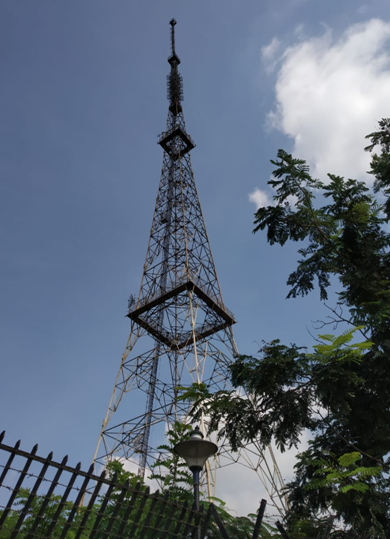
Macrocell base stations have power outputs of typically tens of watts. Macrocell performance can be increased by increasing the efficiency of the transreciever. The antennas for macrocells are mounted on ground-based masts, rooftops and other existing structures, at a height that provides a clear view over the surrounding buildings and terrain. From Fig3 we can get an idea that macrocell has larger cell radius and interconnections can be made.

Summary:

  • Small cells are nothing but small base stations which acts like repeaters.
  • Femtocells are used in IOT due to energy efficiency.
  • Macrocells and Femtocells when connected gives advanced smart home features.
  • Wi-Fi is a small cell but does not operate in licensed spectrum.
  • Shadowing effects can be eliminated by replacing picocells with numerous low-powered femtocells.


Tuesday, April 21, 2020

RADIO PHRASEOLOGY

RADIO PHRASEOLOGY

Messages through Radio requires both in civil and military conditions. Therefore now we can learn about radio phraseology used for the purpose of Radio transmissions along with some military procedures.
RULES FOR RADIO COMMUNICATION
1. Before you press the transmission button, gather your thoughts about what you are going to say. Many people with radios have a tendency to talk and/or repeat too much. Say what you want to say without unnecessary repeats. Keep in mind that your message should go through the first time – you may not have any opportunity to repeat it.
2. Offer the call sign of the unit you are calling first. It will make the recipient aware of spotlight on the approaching message. There may be more audience members and radio system clients so you should tell them that this time there will be a message for them, not a usual background noise.
3. Introduce yourself by your call sign.
4. Don’t be too fast in delivering the phrases, give a pause and try to make the listener understand the phrases.
5. Use “CLEAR”, “OVER”, “OUT” when you finish your message.
6. When you have understood the message, acknowledge the receipt with the words such as COPY, RECEIVED, ACKNOWLEDGED.
7. Use "BREAK, BREAK" at whatever point there is a radio traffic and you need to traverse with your crisis message.
8.   Answer each call to confirm reception.
9. On the off chance that you don't fathom the message, don't affirm it. Use "SAY AGAIN", "Rehash", "Hold on."
10. Whenever a word must be spelled use NATO code words for each letter.


QUALITY OF TRANSMISSION

If there should arise an occurrence of some interference or just to affirm how your message was gotten you may need to get some information about the gathering. In this case we use "HOW DO YOU COPY?" or much shorter "HOW COPY?" To get some information about general nature of the gathering you may also ask "HOW DO YOU READ?"
You may simply answer “COPY LOUD AND CLEAR” (”LIMA CHARLIE”)

The meaning of numbers used in assessment over the radio:
1 = Bad (unreadable)
2 = Poor (readable now and then)
3 = Fair (readable but with difficulty)
4 = Good (readable)
5 = Excellent (perfectly readable)
NATO code words for English letters


NUMBERS IN RADIO TRANSMISSION

It is common to say numbers with each digits separately. For example “CHARLIE TWO-THREE” instead of “CHARLIE TWENTY THREE.”


Tuesday, April 14, 2020

HANDHELD TRANSCEIVER

HANDHELD TRANSCEIVER

Handheld transceiver commonly known as walkie talkie otherwise known as handy are commonly used by HAMians to communicate in HAM frequency which is portable and it is two way radio. It was developed by during Second world war mainly first by Mr.Donald hings and then by teams at motorola. First developed Handheld transceiver used vaccum tubes, Whip antenna and powered by high voltage dry cell batteries.
Popular Handheld transceiver manufacturing companies are YAESU , BAOFENG.
Handheld transceiver works in half way duplex mode. Different models differ mainly in range, operating bands, filters ( which filter harmonics).
WORKING OUTLINE:
The process involved in handheld transceiver differ from model to model as they involve different features.
This shows important blocks of a general Handheld transceiver. In  Receiving process the  when PTT is pressed the antenna converts EM signal to electrical signal then amplified , mixed with signal from oscillator , filtered , amplified mixed again to produce Intermediate Frequency (IF) fed to speaker. The process happens reverse in Transmitter mode.
SWITCHING BETWEEN TX , RX
Using Handheld transceiver is simple first set the frequency to receive signals( Receiving mode) and press PTT( push to talk) to Transmit.
MAIN COMPONENTS:
Handheld transceiver use whip antenna because it is compact and has omni directional radiation pattern so less energy is transmitted in vertically upside which is wasted. The signal processing are done by amplifier,tuner, microcontroller,transceiver chip like AT1846S. Powered by rechargable chemical batteries made of lithium ion, NiMH, lithium polymer. Range of power needed vary from 1W to 8W

COMPARISON WITH BASE STATION:
Comparing with base station which is stationery it is movable less power but range is less
WHO CAN USE?
 Restrictions depends on frequency and country.
Commercial license is necessary for using commercial Handheld transceiver. One can use Handheld transceiver in HAM frequency after getting HAM license.
ADDITIONAL FEATURES:
Nowdays Handheld transceiver include additional features that were not present in first made Handheld transceiver such as NOAA weather alerts, Memory channels, head phone jack, bluetooth, SOS alarm etc.


Tuesday, April 7, 2020

All India Radio(AIR) - Coimbatore

All India Radio(AIR), CBE - Ramanathapuram and Chettipalayam

All India Radio(AIR) - Coimbatore is one of the nodal centres for FM radio broadcasting. In Coimbatore “Rainbow FM - 103MHz” is being broadcasted at respective slots in the radio community. Do you know the background skeleton of broadcasting Rainbow FM and other programs of chennai and delhi?
Let’s explore!

Coimbatore radio station broadcasts "Rainbow FM 103 MHz" and it also broadcasts the programs from Chennai and Delhi. The programs from Chennai and Delhi will be transmitted to Coimbatore (All India Radio Station) through the GSAT-10 satellite. The GSAT-10 is a Indian communication satellite which has 30 transponders consisting of KU bands and C bands. In All India Radio, the dish (parabolic reflector) antenna receives the signal from the GSAT-10 satellite. This satellite is 35,600 kilometres away from the earth surface. The signal from the satellite travels 35,600 kilometres and reaches the parabolic reflector antenna in the range of nano (or) pico (or) femto watts. This received signal is processed in the AIR, Ramanathapuram. The processed signal will be sent to Podanur Chettipalayam station through a microwave link.


Fig. 1 : Dish antenna - (AIR-Ramanathapuram)

The above figure(fig.1) is the dish antenna with parabolic reflector which is installed to receive the signal from GSAT-10 satellite. This antenna is located at AIR-Ramanathapuram.

Near Podanur, Chettipalayam station is the place where the programs are broadcasted around Coimbatore. This is located 10 kilometers away from AIR-Ramanathapuram.

In Chettipalayam station, there is a microwave antenna to receive the signal from AIR-Ramanathapuram. The received signal will be processed in Chettipalayam station and broadcasted  around coimbatore.
Can you guess why the two stations are isolated??

The need of Chettipalayam station is to boost the signal power. Here, In Chettipalayam, the signal is boosted to the power of 10,000 watts(10KW). One of the deciding factors to  transmit a signal over a long distance is power (signal’s power). To transmit a signal all around Coimbatore, we need large power to carry that signal. So that it would reach the people all around Coimbatore.

The below figure(fig.2) is the tower which is set up in Chettipalayam station for FM broadcasting and microwave reception. This tower will receive the signal from AIR-Ramanathapuram using microwave antenna and the received signal is boosted to 10KW at the station and via the array antennae, boosted signal is broadcasted to all around Coimbatore. This tower is also shared by “Hello FM - 106.4MHz”. In this tower, two types of antennae are used. One is microwave antenna(fig.3) which is used for receiving signal from AIR-Ramanathapuram and other is array antenna(fig.4) which is used to transmit or broadcast FM signal,


Fig. 2 : Tower - Chettipalayam station

The below figures(fig. 3 and fig.4) shows the two types of antennae placed in the tower. This tower is located in Chettipalayam station.


Fig. 3 : Microwave antenna


Fig. 4 : Array antenna